Road and terrain
The whole road project, from the survey point to the mass haul diagram, runs in the same file. Superelevation and spirals follow KGM (General Directorate of Highways).
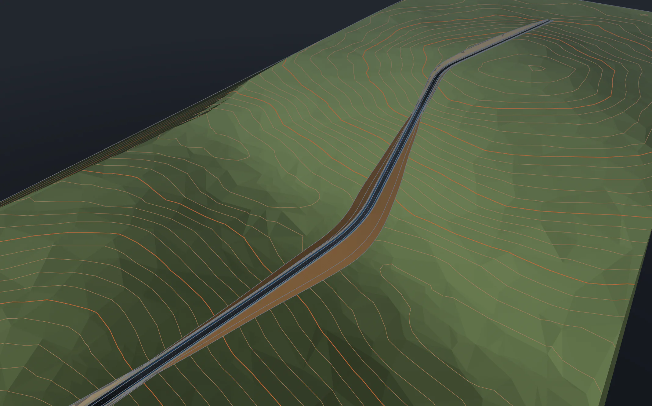
Terrain
The terrain surface is built from the data you have. Satellite imagery and institutional background maps are placed behind the drawing.
- Points and TINSurface from survey points
- Point cloudLAS and LAZ files
- Background mapsSatellite imagery and institutional background maps
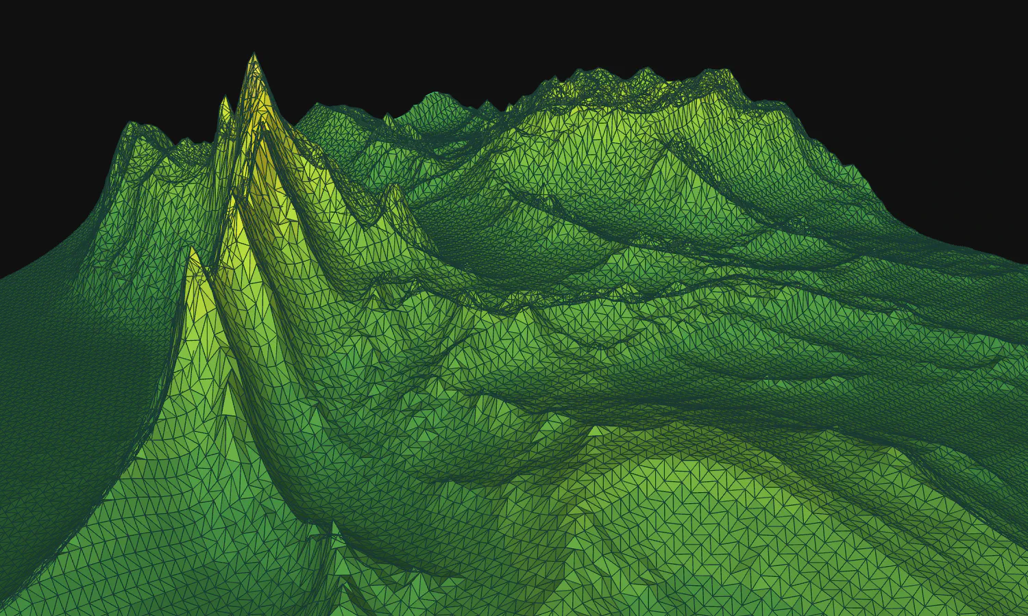
Points and surface
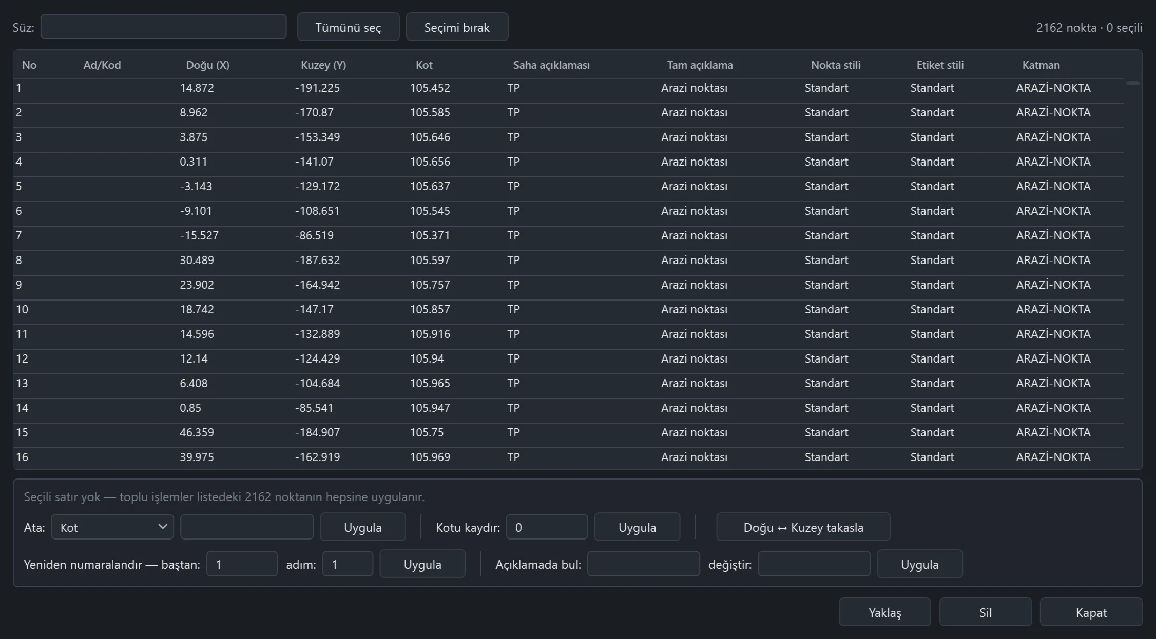
Survey points are managed in a single table. The surface is built from whatever data you have.
- Point editorFiltering, bulk elevation assignment, renumbering
- Point groupsGroups by rule, display settings per group
- Surface sourcesPoints, elevation labels, triangles, DEM and LandXML
- Surface toolsExtracting contours and boundary lines, offsetting the surface
Ground investigation
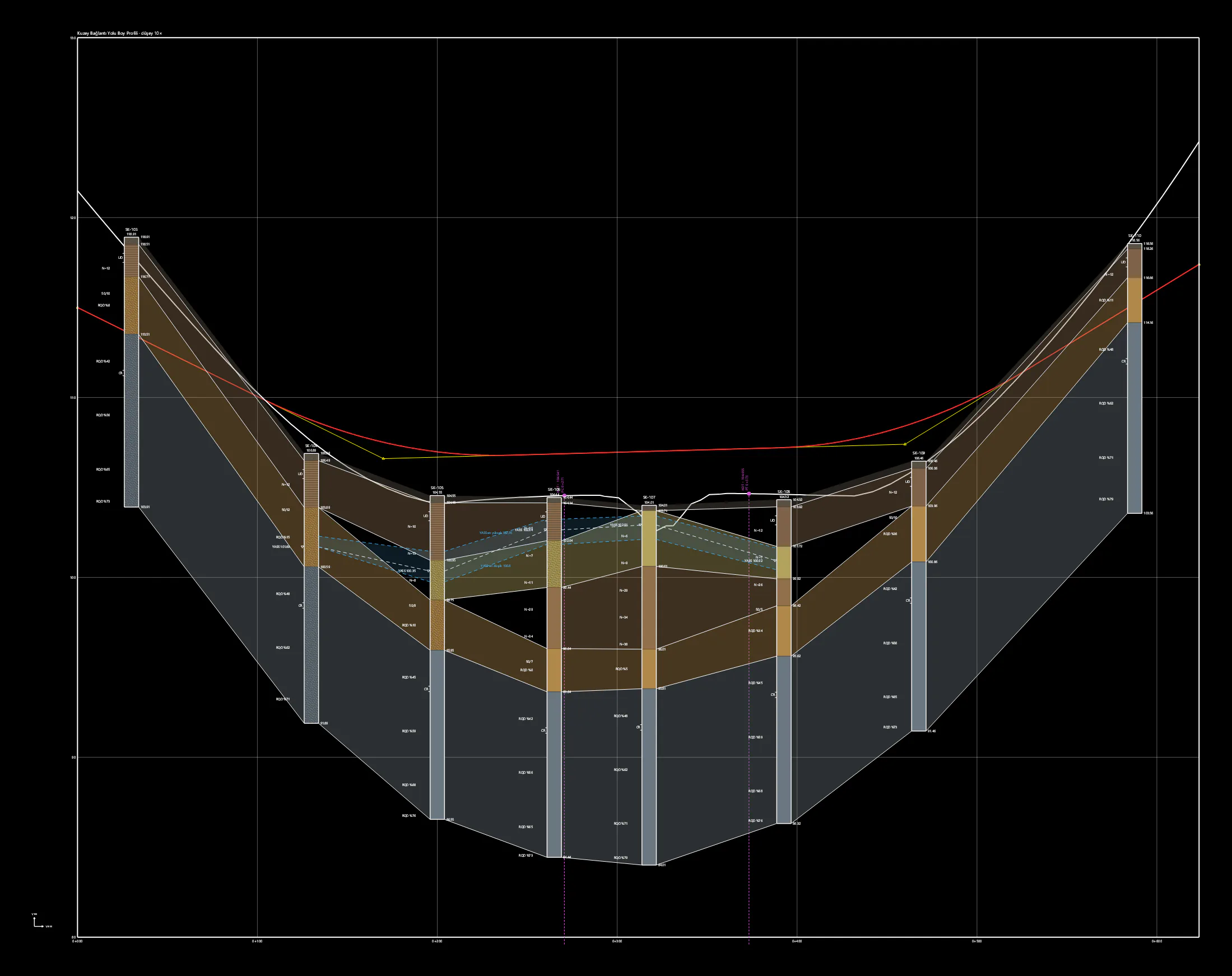
Borehole data is brought into the drawing. Strata and groundwater appear at the boreholes' positions on the longitudinal profile.
- DataFrom Excel, CSV and AGS4 files
- Columns on the profileStratum, SPT and groundwater in each borehole column
- Stratum surfaceA stratum surface is built between boreholes
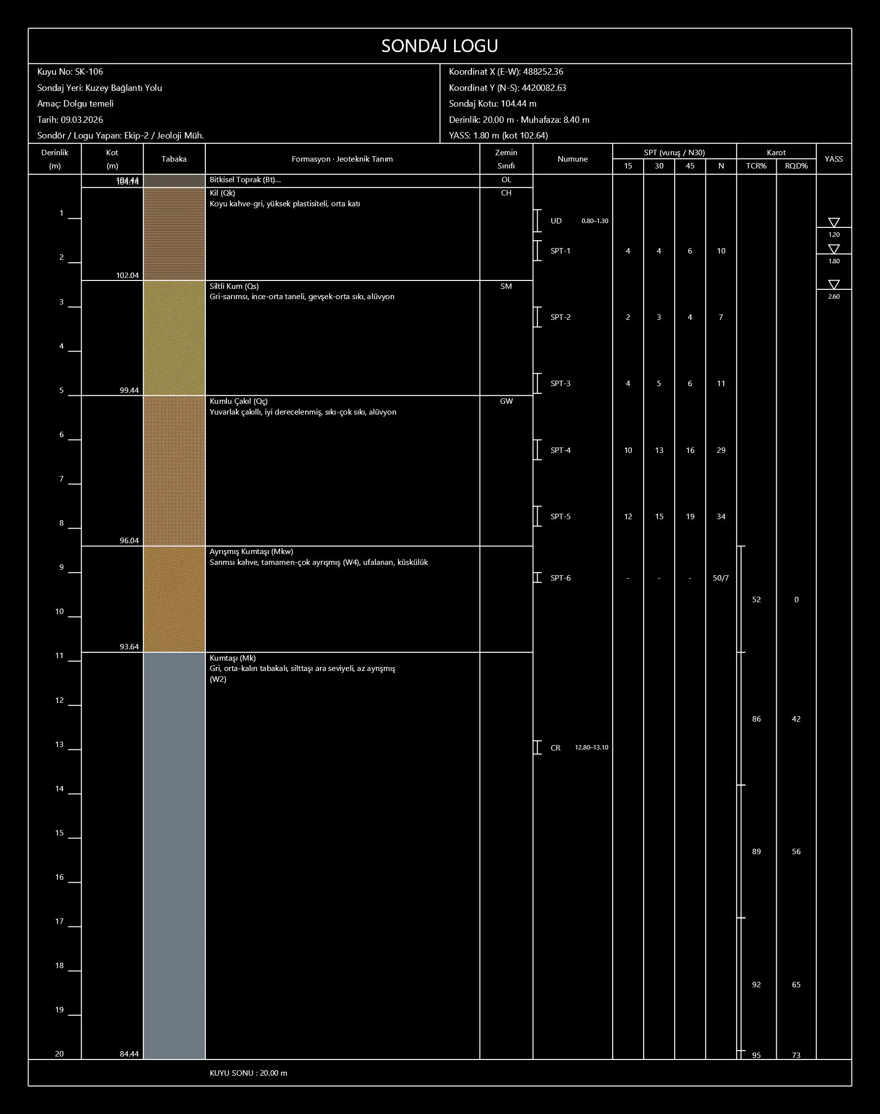
Borehole log
Each borehole's log is drawn as a sheet: strata, tests and groundwater by depth on the same page.
- StrataWith a depth ruler and soil-class hatching
- TestsSPT, sample and core values
- GroundwaterMeasured levels
Alignment
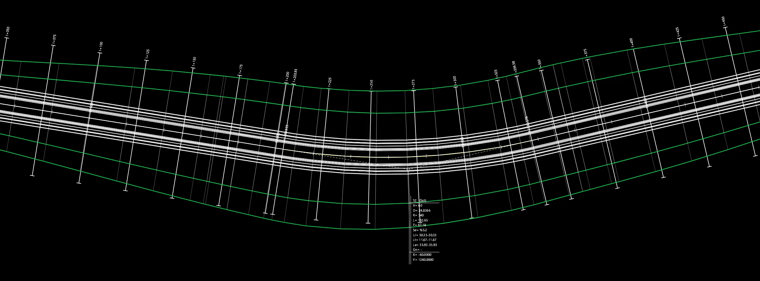
Horizontal geometry is built with curves and spirals (clothoids). Superelevation and plan display follow KGM practice.
- Curve and spiral (clothoid)The transition curve is a clothoid
- SuperelevationCalculated per KGM
- Plan displayCurve data block and superelevation band
Profile and design profile
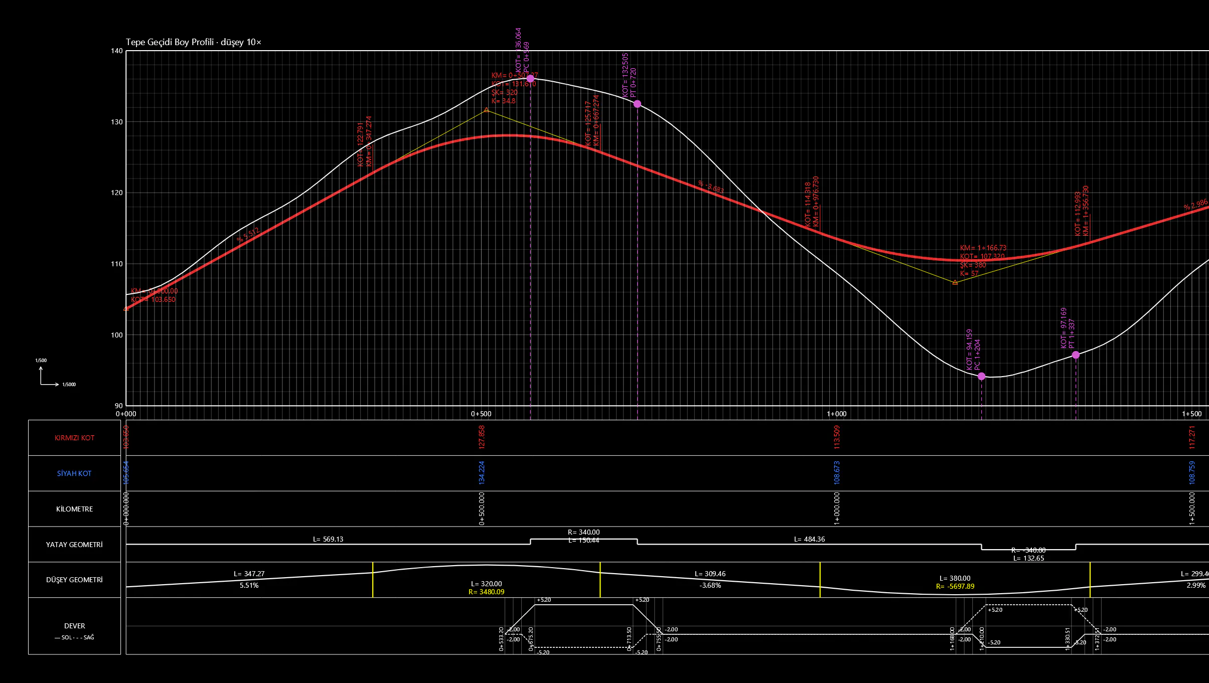
The design profile is drawn on the longitudinal profile. Vertical curve values come from the KGM handbook tables.
- Longitudinal profileOn the terrain profile
- Design profileTogether with the vertical curve
- Superelevation bandBelow the profile, by chainage
Typical section
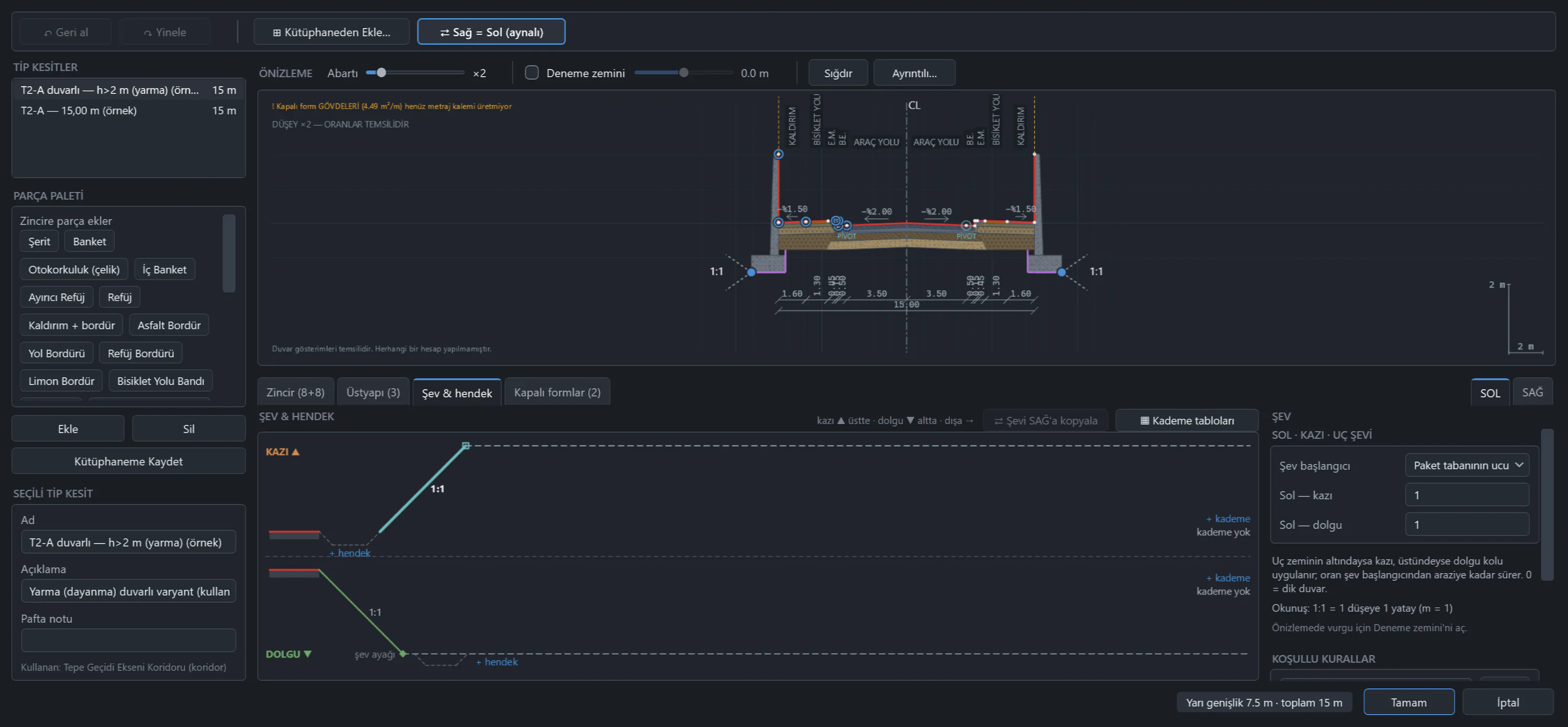
The road cross-section is defined piece by piece: lane, shoulder, cycle path, pavement, slope, wall. Ready-made sections come from the KGM library.
- LibraryKGM typical section library
- PreviewThe section is redrawn as you change it
- Section from drawingA definition is extracted from an existing section drawing
Corridor
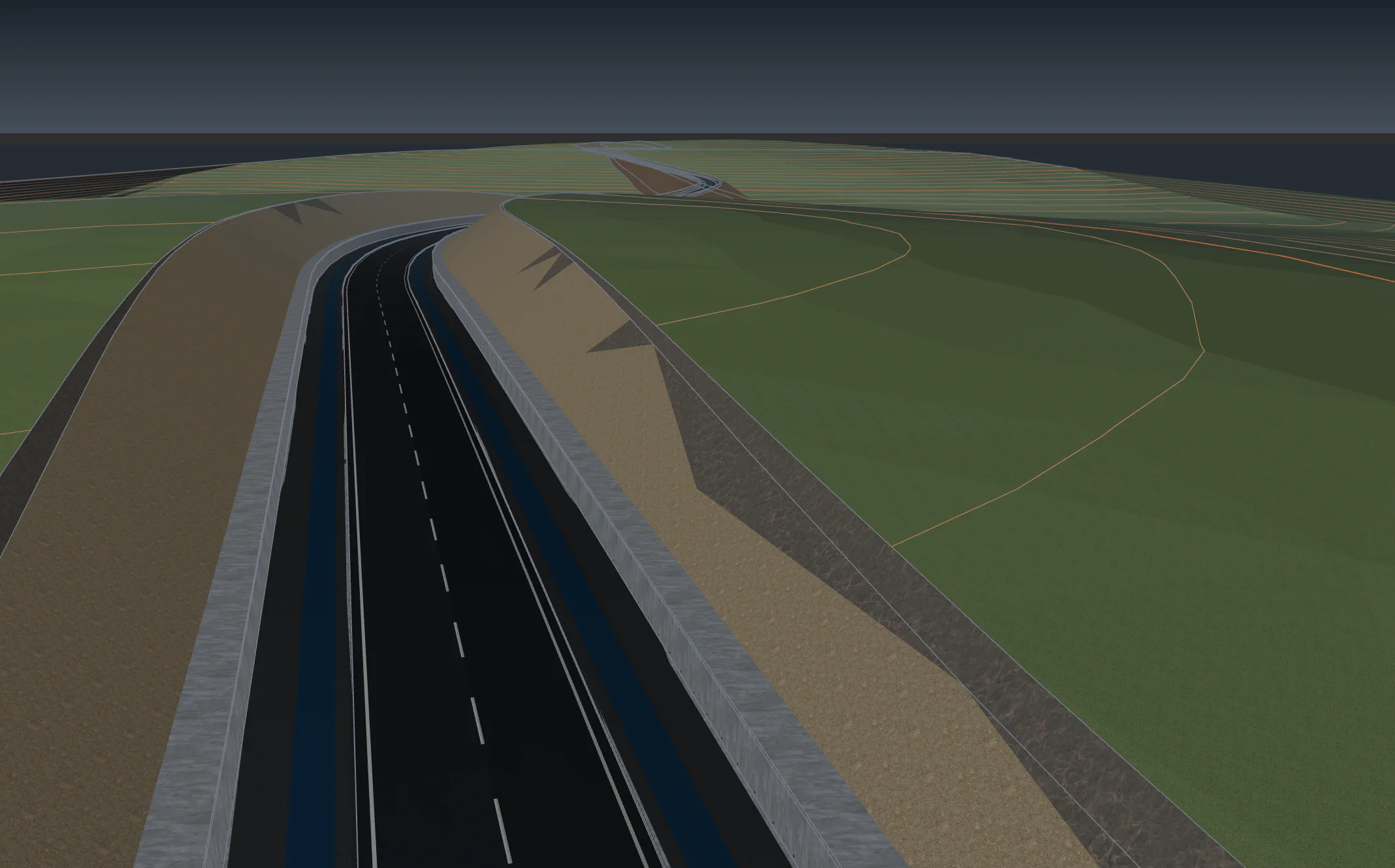
When the alignment, design profile and typical section come together, the 3D road model, the corridor, is created.
- 3D modelLanes, pavement, slope and wall sit on the terrain
- IntersectionAt-grade intersection and roundabout
- Corridor surfaceSurfaces and lines are extracted from the corridor
Earthwork volumes
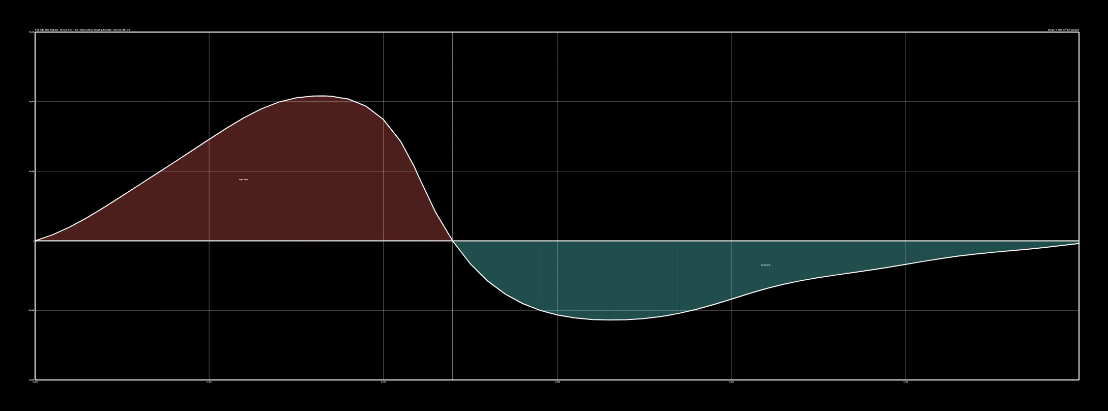
Cut and fill volumes are calculated from the road model.
- Cut and fillBy soil class
- Mass haul diagramHaul-balanced
- Periodic volumesDelivered as an Excel file
- Volume dashboardAll volume results in one table
- Volume between two surfacesCut and fill between two surfaces
Excavation design and site grading
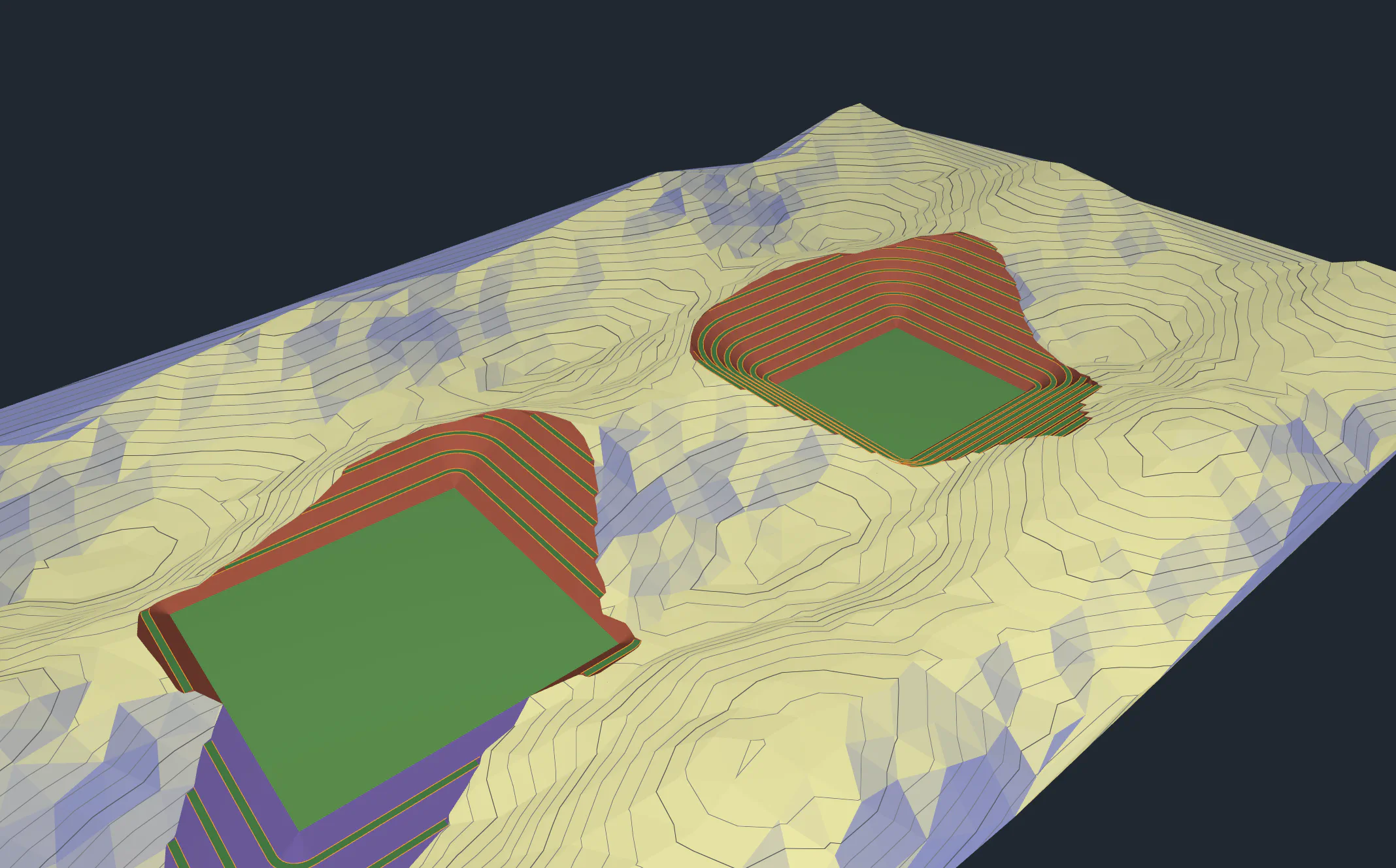
A foundation pit, a platform or site grading is defined by a formation level and slopes; the volume is calculated right away.
- Excavation designFormation level, slope gradient and benches
- Site gradingCut and fill for a site
- 3D resultFormation and slopes are shown on the terrain
Sheets
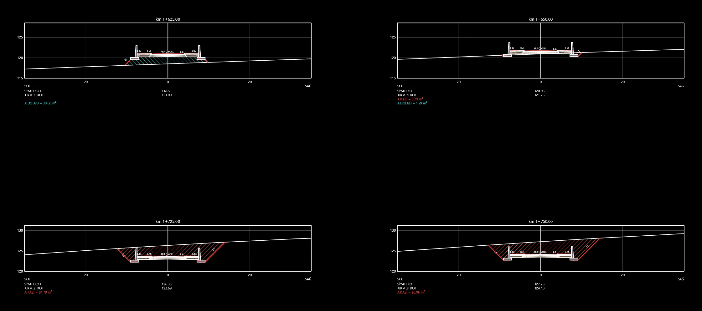
The sheets to be delivered come out as DXF.
- Longitudinal profileDXF
- Cross-sectionDXF
- Earthwork volume scheduleXLSX or CSV
Outputs
| Deliverable | Format |
|---|---|
| Longitudinal profile sheet | DXF |
| Cross-section sheets | DXF |
| Earthwork volume schedule | XLSX · CSV |
| Mass haul diagram | DXF |
| Periodic volumes | XLSX |
| Alignment and surface data | LandXML |
Plainly: what it does not do
- It does not write DWG (drawings are delivered as DXF).
- It does not produce a PDF of the sheets.
- It does not calculate retaining walls; the wall shown in a section is representative.
- Road rehabilitation is out of scope.
Related demos
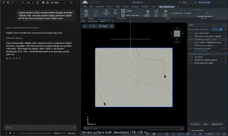 0:27
Terrain from a points file
A survey file is read, the terrain surface is built and the elevation range is reported.
Road and terrain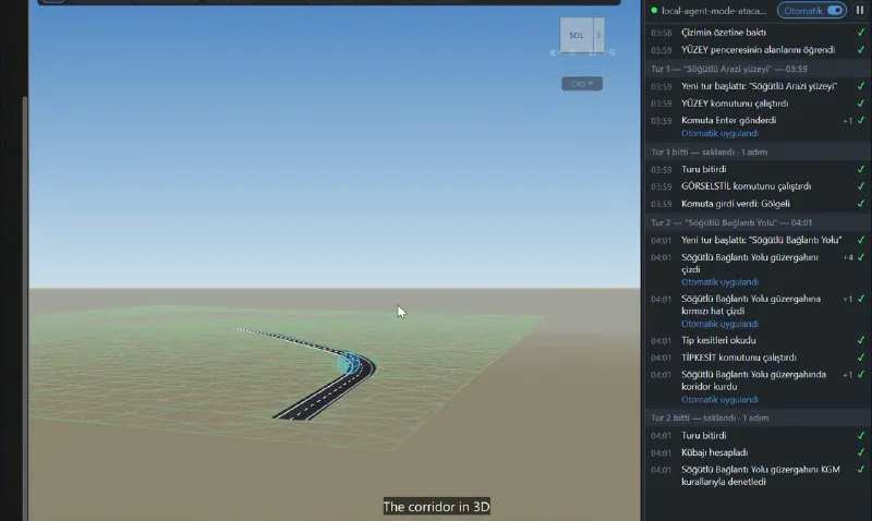 0:50
Road: alignment, section, earthwork volumes
Alignment, design profile, typical section and corridor are built with a single prompt; cut and fill volumes are calculated.
Road and terrain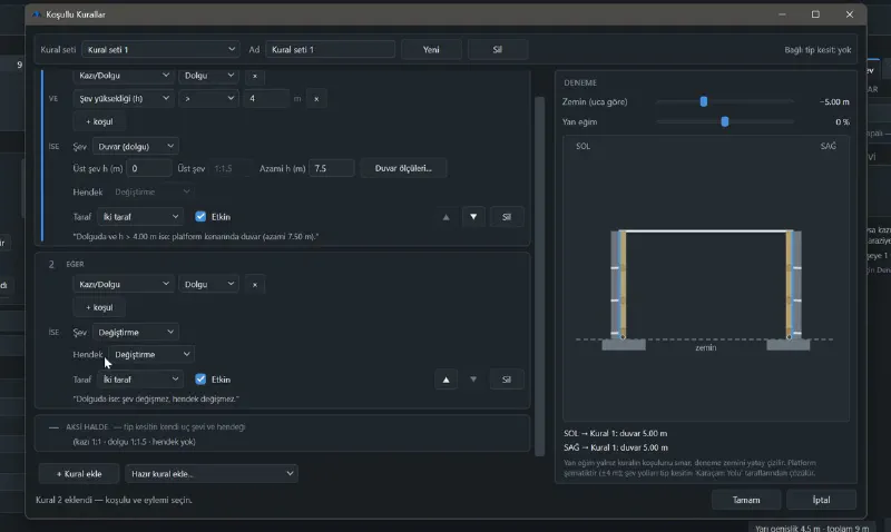 1:41
Typical section rules
A rule is written once; at each station the program decides whether it will be a slope, a wall or a ditch.
Road and terrain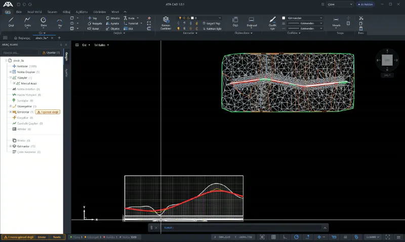 1:34
Superelevation and KGM built-up section
Superelevation is calculated to KGM criteria and applied to plan and profile. A typical section with a cycle path is assigned to the built-up section.
Road and terrain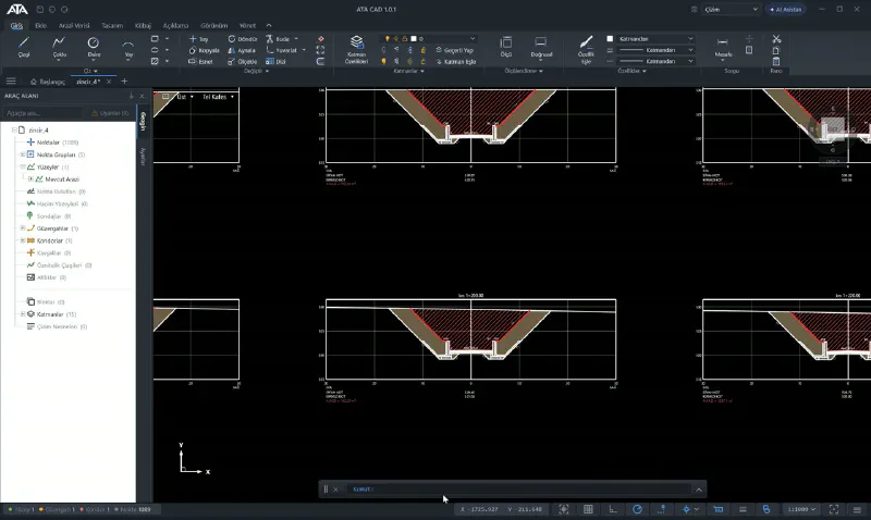 1:25
Cross-section sheet and quantity take-off
The section of every station is arranged on the sheet; cut, fill and quantity items come out of the same model.
Road and terrain